
Wire insulation temperature ratings call out a different rating for “wet” vs “dry”. There would be no area that would normally be “wet”. Length of the run from the new shore power inlet (including a new breaker I will mount within a foot or so of that inlet) would be about 33 feet. However, my intent is to run a new AC 30amp (120v) shore power line that would be housed in a sort of chase-way that exists near where the deck and the hull meet. The wire size calculator mentions that the length need to include the “round trip”.
#Wire gauge amp chart 24v iso
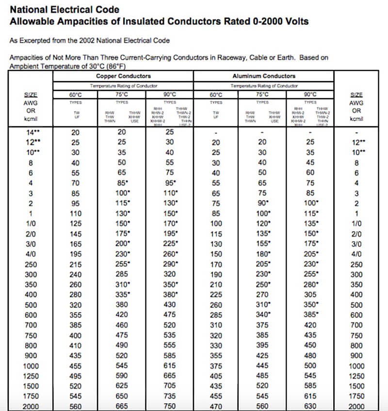
Our wire size calculators use a formula that is based on Ohm's law in order to calculate a diameter for the conductor that keeps the voltage drop below the value you set in the calculator.Īccording to both ISO and ABYC standards, the voltage drop should be kept below 10% in all cases and below 3% for sensitive or safety relevant consumers such as navigation lights, bilge pumps and main feeder cables for switch panels. So when we have longer cable runs, we also need larger diameter conductors, or else the resistance and voltage drop goes too high. The longer and smaller diameter the concuctor the higher it's cumulative resistance. is the voltage that gets lost on the passage from the battery to the consumer and back to the battery as a result of resistance in the conductor. Our calculators use the ABYC and ISO Ampacity Tables as the basis for these calculations. The number of current carrying conductors that are bundled together.The ambient temperature (whether part of the conductor runs through an engine compartment or not), and.The maximum temperature rating of the conductor's insulation,.But there are three other factors that come into play: The greater the diameter of the conductor, the more amps can flow through it without it reaching a critical temperature. is the maximum amount of current that a conductor can carry safely without overheating and melting down it's insulation. The wire size calculators calculate the required size of the conductor based on two factors: the maximum ampacity and the voltage drop. In the ABYC version we have a box to check if the conductor is used in an AC-circuit because with the ABYC the derating factors for bundled AC conductors vary from DC conductors.Note also that the AC grounding conductor (green or green and yellow) and any bonding conductors (the same color) are not normally current-carrying and so do not count in the bundling calculation. Note that you have to check the engine compartment box even if only a small section of the cable run leads through the engine room. Now we select the number of current-carrying conductors that are bundled together, for example in the same cable trunk or wiring harness and whether or not the conductor is installed in an engine compartment.Note, however, that cables with a 60° Celsius rating on the insulation are not allowed to be installed in engine compartments!

In this case, we recommend that you leave the setting at the 60° Celsius (140☏) setting to be on the safe side. In other parts of the world, this is unfortunately not always required. In the US, this should be printed on the conductor's insulation. The next setting is the temperature rating of the conductor's insulation.If you want to, you can also set a custom value. For less important loads you can also set it to 10%, but we recommend to start with the 3% setting and only change it if the required wire sizes become excessive. The maximum voltage drop is preset to 3%, which is required for safety relevant devices.Now we set the system voltage, which on boats is typically either 12 or 24 Volts in a DC system and 120 or 230 Volts in an AC-system.This should be written on the back of the devices or found in their data sheets. We can choose either Amps or Watts as the unit. Now we set the maximum total load of the consumer(s) that are connected to the conductor.For the ISO-Version we have preset this to meters, for the ABYC version to feet. This cable run has to include the length of the positive and the negative wire! We can choose the unit for the length between meters or feet. First of all we need to set the length of the total cable run from the battery to the consumer and back, or, in some cases, the point of connection of the circuit (for example, a circuit breaker in the main panelboard).


 0 kommentar(er)
